Saturday, November 21, 2009

the city: the raised prefab city


the city is a field of layers which is differentiated in to many defined areas, it is a space which needs heterogeneity of spaces in order to be inhabited.
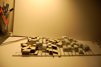


A grid structure of 10mt was tested on the scale of the full site . Blocks were placs in to the structure as simple squares prefab elements.


possible city vision in elevation

diagram of blocks (red) being inserted in to the grid structure.


a city must provide dialoge between citizens, connections continuity and it should allow changes in the system.
the city is elevated from the ground. It has a system wich use a wire structure to generate connections and areas for the blocks that need to be inserted.


Tuesday, November 17, 2009

urban field - testing the layering system on 1:500 scale

as we studied in the previus tests the module from plan seems be always the same pattern.


Althought in plan the module is the same as the 2d pattern in the 3d axo the system starts generate different spaces which affect the elevation of each side of the module.


the test was moved to bigger scale sperimenting the module on a big area.
the module was mirrored horizontally and verticaly and it generated an interesting urban field that has multiplicity of spaces such as : many blocks sizes, links of different scale, different heights, and alternating relation between solids and voids .

this is a good start in order to analyze urban field systems.


Monday, November 16, 2009

pattern research : the urban field

the following studies analize the patter as a system which could generate different fields for a urban layout.

the rule used is insipred by the one used to generate the 2d pattern: the layering system


slice of the pattern tested on site


the squar e area for the model was selected area from the pattern in order to test the model on scale 1:500

second option: sliding the leyers


As we can see in the image above each layer of the model is around 2mm that in scale 1:500 corrispond to only to 1 mt. In order to start analyze urban field we need to get the proportions right therefore in the following studies the layers are changed to scale and each of them measure 3 mt.


the smaller blocks measure 5 mt going up to a max of 20 mt.


elevation density: the previus systems were generated by layers of same plans what if we change the elevation density of the system?
( see image below)

prefab studies/ jean prouvè / tropical house 1949


Wednesday, November 11, 2009

links and DENSITY


In th eprevius system (see images above) was studied the condition of a mirrored line which develop a grid from which are defined all the components of the system : solids, voids , links


The next studies will be focus on understanding how those links could change their properties and how could be modifed the pattern's density.
in order to generate a system that allows more multiplicity and heterogeneity the grid is changed from the previus pattern.


Thursday, November 5, 2009

DISTORTION

The grid's lines are rotated and mirrored.


Test of the pattern in 3D :
The pattern from the top is always a 2D image, when it come to a more complex 3D space all the pattern components start generating new floors, and different spaces.
Every floor in the model is te inverse of the floor below , this system reflect the mirror rule used for the composition of the pattern.


test on site


DENSITY

In the previous patterns (image below) the density test was only sperimented by dimantling the pattern's modules.


The following pattern are generated by scaling the grid size and therefore change the pattern density.


The density change only on the grid scale and not on the solid components (the black and white filled areas, see image below).


Pattern F - Density studies- Triangles modules


It is interesting to see that the density change both on grid scale and on the solid components (the black and white filled areas). Infact black and white colors are still arranged on 2 alternate colors but their density is different from the previous square pattern ( see image above)


The pattern density is even more strong when we delete the grid.


The question is how could this pattern be represented in a 3D space? (°.°)

patern A tested in the 3d space